Source Code
Point, Lines and Polygons
Each geometric object is described by a set of vertices and the type of primitive to be drawn. A vertex is no more than a point defined in three dimensional space. Whether and how these vertices are connected is determined by the primitive type. Every geometric object is ultimately described as an ordered set of vertices. We use the glVertex*() command to specify a vertex. The '*' is used to indicate that there are variations to the base command glVertex().
Some OpenGL command names have one, two, or three letters at the end to denote the number and type of parameters to the command. The first character indicates the number of values of the indicated type that must be presented to the command. The second character indicates the specific type of the arguments. The final character, if present, is 'v', indicating that the command takes a pointer to an array (a vector) of values rather than a series of individual arguements.
For example, in the command glVertex3fv(), '3' is used to indicate three arguments, 'f' is used to indicate the arguments are floating point, and 'v' indicates that the arguments are in vector format.
Points: A point is repesented by a single vertex. Vertices specified by the user as two-dimensional (only x- and y-coordinates) are assigned a z-coordinate equal to zero. To control the size of a rendered point, use glPointSize() and supply the desired size in pixels as the argument. The default is as 1 pixel by 1 pixel point. If the width specified is 2.0, the point will be a square of 2 by 2 pixels. glVertex*() is used to describe a point, but it is only effective between a glBegin() and a glEnd() pair. The argument passed to glBegin() determines what sort of geometric primitive is constructed from the vertices.
Source Code |
Lines: In OpenGL, the term line refers to a line segment, not the mathematician's version that extends to infinity in both directions. The easiest way to specify a line is in terms of the vertices at the endpoints. As with the points above, the argument passed to glBegin() tells it what to do with the vertices. The options for lines includes:
GL_LINES: Draws a series of unconnected line segments drawn between each set of vertices. An extraneous vertex is ignored.
GL_LINE_STRIP: Draws a line segment from the first vertex to the last. Lines can intersect arbitrarily.
GL_LINE_LOOP: Same as GL_STRIP, except that a final line segment is drawn from the last vertex back to the first.
With OpenGL, the description of the shape of an object being drawn is independent of the description of its color. When a paraticular geometric object is drawn, it's drawn using the currently specified coloring scheme. In general, an OpenGL programmer first sets the color, using glColor*() and then draws the objects. Until the color is changed, all objects are drawn in that color or using that color scheme.
Example: | Source Code |
Polygons: Polygons are the areas enclosed by single closed loops of line segments, where the line segments are specified by the vertices at their endpoints. Polygons are typically drawn with the pixels in the interior filled in, but you can also draw them as outlines or a set of points. In OpenGL, there are a few restrictions on what constitutes a primitive polygon. For example, the edges of a polygon cannot intersect and they must be convex (no indentations). There are special commands for a three-sided (triangle) and four-sided (quadrilateral) polygons, glBegin(GL_TRIANGLES) and glBegin(GL_QUADS), respectively. However, the general case of a polygon can be defined using glBegin(GL_POLYGON).
Example: | Source Code |
Drawing 3-D Objects
GLUT has a series of drawing routines that are used to create three-dimensional models. This means we don't have to reproduce the code necessary to draw these models in each program. These routines render all their graphics in immediate mode. Each object comes in two flavors, wire or solid. Available objects are:
Transformations
|
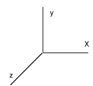
A modeling transformation is used to position and orient the model. For example, you can rotate, translate, or scale the model - or some combination of these operations. To make an object appear further away from the viewer, two options are available - the viewer can move closer to the object or the object can be moved further away from the viewer. Moving the viewer will be discussed later when we talk about viewing transformations. For right now, we will keep the default "camera" location at the origin, pointing toward the negative z-axis, which goes into the screen perpendicular to the viewing plane. |

|
When transformations are performed, a series of matrix multiplications are actually performed to affect the position, orientation, and scaling of the model. You must, however, think of these matrix multiplications occuring in the opposite order from how they appear in the code. The order of transformations is critical. If you perform transformation A and then perform transformation B, you almost always get something different than if you do them in the opposite order.
Scaling: Translation: This program will create a triangle, shrink it using a scaling factor less than 1.0 and translate it to another location.
Rotation: This program will create a cube and rotate it by 45 degrees.
Display Lists A display list is a group of OpenGL commands that have been stored for later execution. When a display list is invoked, the commands in it are executed in the order in which they were issued. Most OpenGL commands can be either stored in a display list or issued in immediate mode, which causes them to be executed immediately. A display list must be bracked with the glNewList() and glEndList() commands. The argument for glNewList() is the unique name that identifies the list.
A display list contains only OpenGL commands. The values in the display list can't be changed and it is not possible to either add or remove commands from the list once it has been stored. You can delete the entire display list and create a new one, but you can't edit it.
The command glNewList() specifies the start of a display list. The first parameter is a nonzero positive integer that uniquely identifies the display list. The second parameter specifies whether the OpenGL command should be executed immediately as well as placed in the display list (GL_COMPILE_AND_EXECUTE) or just added to the display list without executing them (GL_COMPILE). The comand glEndList(), obviously, specifies the end of a display list.
After you have created a display list, you can execute it by calling glCallList(). With glCallList(), you can execute the same display list many times, call a display list from another routine, or mix calls to execute display lists with calls to perform immediate-mode graphics. Any changes in the current color and current matrix made during the execution of the display list remain in effect after it has been called. Therefore, manipulating the matrix stack may be required to change the state of the variables before executing a display list and then restoring these values after the list has been executed.
It is important to note that OpenGL commands are not necessarily executed as soon as they are issued. It is necessary to call the command glFlush() to ensure that all previously issued commands are executed. glFlush() is generally called at the end of a sequence of drawing commands to ensure all objects in the scene are drawn before beginning to accept user input.

Source Code

Source Code
glNewList(1,GL_COMPILE);
glColor3f(1.0, 0.0, 0.0); // red
glBegin(GL_TRIANGLES);
glEnd();
glTranslate(1.5, 0.0, 0.0); // move object
glEndList();

Source Code